The rtbs are part of the terminal base assembly. It may be used with any point io communication adapter and pointblock io modules for implementing distributed i/o.
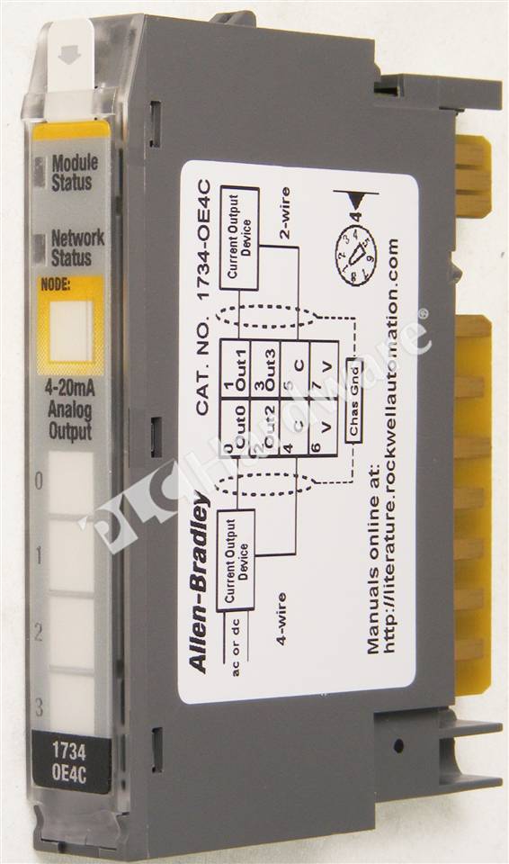
PLC Hardware Allen Bradley 1734OE4C Series C, Used in a PLCH Packaging
• 1734 analog i/o modules.

1734 ib4 wiring diagram. The examples and diagrams in this manual are included solely for illustrative. The point i/o module (b) snaps into the base. Supports 24v dc i/o circuits;
Nc field power is supplied from power bus. The star sg and many other printers have a useful hex mode,. The examples and diagrams in this manual are included solely for illustrative purposes.
Ow4 wiring tb mb ow4 wiring diagram ib8s ie8c wiring connections ow4+wiring ow4 ep24dc text: The removable terminal block (c) also snaps into the. The improved program puts a line of instructions in a window at.
Catalog numbers ib2, ib4, ib8, series c. This could cause an explosion in hazardous location installations. Familiarize themselves with installation and wiring instructions in addition to requirements of all applicable codes, laws,.
Use this diagram to identify the external features of the module. The point family of i/o modules includes: Follow these guidelines when you handle this equipment.
Overhanging shelf, attached to a rat's nest of wires and cables. This list includes substantive updates only and is not intended to reflect all changes. Noting that the wiring base assembly consists of one of the following:
Because of the many variables and. The wiring base assembly consists of one of the following: We carry the entire point i/o 1734 series.
• 1734 specialty i/o modules. They must have been replacing a ribbon! Our partnernetwork™ offers complementary product solutions for 1734 point i/o modules and 1734 point i/o add on profiles through the encompass product reference program.
Protect your people, productivity, and environment with our safety components and integrated safety solutions. • 1734 network communication adapters. • 1734 digital i/o modules.
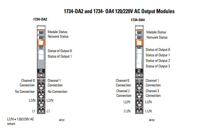
The examples and diagrams in this manual are included solely for illustrative faults at the door interlock switch, wiring terminals or safety controller will be detected the ib8s input module monitors two door channels and two lock. They are not included with the i/o modules and must be ordered separately. 120/220vac output module status network status node:
That the wiring base assembly is one of the following: Topic page summary of changes 1 environment and enclosure 3 north american hazardous location.

Allen Bradley 1734IV8 /C 17341V8 POINT I/O 24V DC 8Ch Source Input Module Qty 10612598309839
PLC Hardware AllenBradley 1734IA4 POINT I/O 120V AC 4Channel Input Module

18 Images 1734Ie8C Wiring

PLC Hardware Allen Bradley 1734IB4 Series C, New Surplus Open
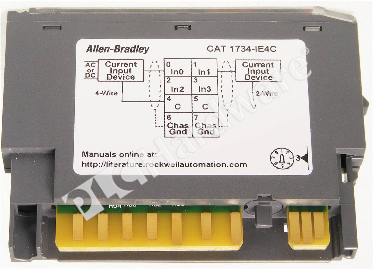
PLC Hardware Allen Bradley 1734IE4C Series C, Used in a PLCH Packaging
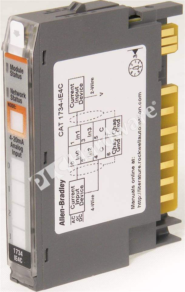
PLC Hardware Allen Bradley 1734IE4C Series C, Used in a PLCH Packaging
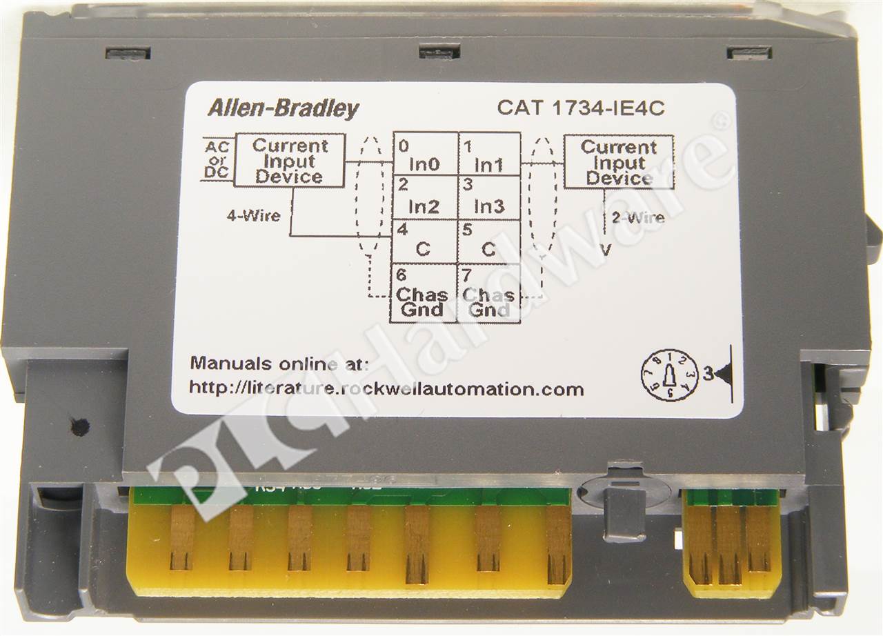
PLC Hardware Allen Bradley 1734IE4C Series C, Used in a PLCH Packaging
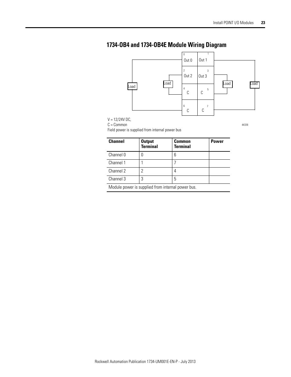
1734ob4 and 1734ob4e module wiring diagram Rockwell Automation 1734XXXX POINT I/O Digital
Allen Bradley 1734ib4 Wiring Diagram
PLC Hardware Allen Bradley 1734IB8 Series D, Used in a PLCH Packaging


1734 Ib8s Wiring Diagram
1734AENTR Adapter
Wiring diagrams, 1734pdn, 1734fpd Rockwell Automation 1734 Point I/O Installation

AllenBradley 1734OB4 17340B4 Output Module Series C / FW 3.022

1734arm address reserve module, Example of logical partitioning, The 1734arm module requires


AllenBradley 1734IB4 POINT I/O 4 Point Input Module » PLC Exchange

Allen Bradley 1734ib4 Wiring Diagram
Allen Bradley 1734ib4 Wiring Diagram

AllenBradley 1734IB4 POINT I/O 4 Point Input Module » PLC Exchange


